

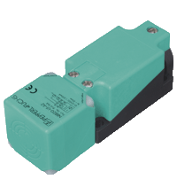
Inductive sensor NBN40-U1K-E2-3G-3D
- Sensor head bidirectional and rotatable
- 4 LEDs indicator for 360° visibility
- 40 mm non-flush
- 3-wire DC
- ATEX/IECEx Zone 2/22


 Contact Us
Please note: All product-related documents, such as certificates, declarations of conformity, etc., which were issued prior to the conversion under the name Pepperl+Fuchs GmbH or Pepperl+Fuchs AG, also apply to Pepperl+Fuchs SE.
Datasheet excerpt: Technical data of NBN40-U1K-E2-3G-3D
| General specifications | ||
|---|---|---|
| Switching function | Normally open (NO) | |
| Output type | PNP | |
| Rated operating distance | 40 mm | |
| Installation | non-flush | |
| Output polarity | DC | |
| Assured operating distance | 0 ... 32.4 mm | |
| Actual operating distance | 36 ... 44 mm typ. 40 mm | |
| Reduction factor rAl | 0.31 | |
| Reduction factor rCu | 0.3 | |
| Reduction factor r304 | 0.74 | |
| Reduction factor rBrass | 0.39 | |
| Output type | 3-wire | |
| Nominal ratings | ||
| Operating voltage | 10 ... 30 V DC | |
| Switching frequency | 0 ... 150 Hz | |
| Hysteresis | typ. 5 % | |
| Reverse polarity protection | reverse polarity protected | |
| Short-circuit protection | pulsing | |
| Voltage drop | ≤ 2 V | |
| Voltage drop at IL | ||
| Voltage drop IL = 1 mA, switching element on | 0.5 ... 2.3 V typ. 0.9 V | |
| Voltage drop IL = 10 mA, switching element on | 0.8 ... 2.2 V typ. 1.4 V | |
| Voltage drop IL = 20 mA, switching element on | 0.9 ... 2.3 V typ. 1.5 V | |
| Voltage drop IL = 50 mA, switching element on | 0.9 ... 2.5 V typ. 1.6 V | |
| Voltage drop IL = 100 mA, switching element on | 1 ... 2.6 V typ. 1.8 V | |
| Voltage drop IL = 200 mA, switching element on | 1.2 ... 2.8 V typ. 2 V | |
| Operating current | 0 ... 200 mA | |
| Off-state current | 0 ... 0.5 mA typ. 0.01 mA | |
| Off-state current TU =40 °C, switching element off | ≤ 100 µA | |
| No-load supply current | ≤ 20 mA | |
| Time delay before availability | 80 ms | |
| Operating voltage indicator | LED, green | |
| Switching state indicator | LED, yellow | |
| Functional safety related parameters | ||
| MTTFd | 1358 a | |
| Mission Time (TM) | 20 a | |
| Diagnostic Coverage (DC) | 0 % | |
| Compliance with standards and directives | ||
| Standard conformity | ||
| Standards | EN 60947-5-2:2007 EN 60947-5-2/A1:2012 IEC 60947-5-2:2007 IEC 60947-5-2 AMD 1:2012 |
|
| Approvals and certificates | ||
| IECEx approval | ||
| Equipment protection level Gc (ec) | IECEx TUR 21.0019X | |
| Equipment protection level Dc (tc) | IECEx TUR 21.0020X | |
| ATEX approval | ||
| Equipment protection level Gc (ec) | TÜV 20 ATEX 8525 X | |
| Equipment protection level Dc (tc) | TÜV 20 ATEX 8526 X | |
| UL approval | cULus Listed, General Purpose | |
| Marine approval | DNVGL TAA0000160 | |
| Ambient conditions | ||
| Ambient temperature | -25 ... 85 °C (-13 ... 185 °F) | |
| Mechanical specifications | ||
| Connection type | screw terminals | |
| Information for connection | A maximum of two conductors with the same core cross section may be mounted on one terminal connection! tightening torque 1.2 Nm + 10 % |
|
| Core cross section | up to 2.5 mm2 , stripped insulation length: 7 mm | |
| Minimum core cross-section | min. 0.5 mm2 (incl. wire-end ferrules when using flexible conductors) | |
| Maximum core cross-section | max. 2.5 mm2 (incl. wire-end ferrules when using flexible conductors) | |
| Connection (system side) | screw terminals , M20 x 1.5 cable gland , usable thread length 9.1 mm , screw-in depth max. 9.1 mm | |
| Housing material | PA | |
| Sensing face | PA | |
| Degree of protection | IP68 / IP69K | |
| Mass | 225 g | |
| Dimensions | ||
| Height | 40 mm | |
| Width | 40 mm | |
| Length | 118 mm | |
| Note | Tightening torque: 1.8 Nm (housing) | |
| General information | ||
| Use in the hazardous area | see instruction manuals | |
Classifications
| System | Classcode |
|---|---|
| ECLASS 13.0 | 27274001 |
| ECLASS 12.0 | 27274001 |
| ECLASS 11.0 | 27270101 |
| ECLASS 10.0.1 | 27270101 |
| ECLASS 9.0 | 27270101 |
| ECLASS 8.0 | 27270101 |
| ECLASS 5.1 | 27270101 |
| ETIM 9.0 | EC002714 |
| ETIM 8.0 | EC002714 |
| ETIM 7.0 | EC002714 |
| ETIM 6.0 | EC002714 |
| ETIM 5.0 | EC002714 |
| UNSPSC 12.1 | 39121550 |
Details: NBN40-U1K-E2-3G-3D
Datasheet: NBN40-U1K-E2-3G-3D
| Datasheet | File Type | File Size |
|---|---|---|
| Datasheet NBN40-U1K-E2-3G-3D | 556 KB | |
| Datasheet NBN40-U1K-E2-3G-3D | 551 KB | |
| Fiche de données NBN40-U1K-E2-3G-3D | 553 KB | |
| Datenblatt NBN40-U1K-E2-3G-3D | 552 KB | |
| Scheda tecnica NBN40-U1K-E2-3G-3D | 552 KB | |
| Datasheet NBN40-U1K-E2-3G-3D | 558 KB | |
| Folha de dados NBN40-U1K-E2-3G-3D | 554 KB | |
| Hoja de datos NBN40-U1K-E2-3G-3D | 553 KB | |
| Datasheet NBN40-U1K-E2-3G-3D | 565 KB |
Documents: NBN40-U1K-E2-3G-3D
| Instruction manuals | File Type | File Size |
|---|---|---|
| Инструкции | 185 KB | |
| Návod k poużití | 176 KB | |
| Instruktions manual | 174 KB | |
| Instruction manual | 175 KB | |
| Kasutusjuhend | 169 KB | |
| Käyttöohje | 169 KB | |
| Manuel d'instructions | 179 KB | |
| Betriebsanleitung | 176 KB | |
| Οδηγίες χρήσης | 188 KB | |
| Handleiding | 175 KB | |
| Instruction manual / Betriebsanleitung | 174 KB | |
| Használati útmutató | 178 KB | |
| Manuale di istruzioni | 175 KB | |
| Lietošanas pamācība | 175 KB | |
| Instrukciju vadovas | 176 KB | |
| Instrukcja obsługi | 178 KB | |
| Manual de instruções | 178 KB | |
| Manual de utilizare | 177 KB | |
| Návod na poużitie | 176 KB | |
| Navodila za uporabo | 174 KB | |
| Manual de instrucciones | 178 KB | |
| Manual | 173 KB | |
| Technical information | ||
| Installation conditions | 195 KB | |
| Einbaubedingungen | 134 KB |
CAD+CAE: NBN40-U1K-E2-3G-3D
| CAD | File Type | File Size |
|---|---|---|
| CAD 3-D / CAD 3-D | STP | 2003 KB |
| EPLAN | ||
| CAE EPLAN Data Portal / CAE EPLAN Data Portal | LINK | --- |
| EPLAN macro EDZ / EPLAN Makro EDZ | EDZ | 62 KB |
Approvals+Certificates: NBN40-U1K-E2-3G-3D
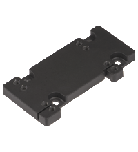
Associated Products: NBN40-U1K-E2-3G-3D
| Accessories | ||||||
|---|---|---|---|---|---|---|
|
||||||
|
||||||


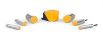
Our amplify article gives interesting insights about the development of the new, modern portfolio of inductive proximity sensors from Pepperl+Fuchs. Get the whole story here!

The knowledge base for inductive sensors contains extensive expertise and supports you in the highly precise and smooth operation of the sensors in your machinery and plants.

The VariKont inductive sensors with Active Shielding Technology ensure high switching distances, no matter the installation situation and the surrounding material. Benefit from easier equipment design and reduced costs!
As the SIL 2/PL d inductive safety sensors have no dead band, data transfer can occur with no minimum distance between sensor and target. Discover the optimized portfolio for demanding environments.


Pepperl+Fuchs Inc.
1600 Enterprise Parkway
Twinsburg, OH 44087
United States of America
sales@us.pepperl-fuchs.com
 +1 330 425-3555
Pepperl+Fuchs is a leading developer and manufacturer of electronic sensors and components for the global automation market. Continuous innovation, enduring quality, and steady growth have been the foundation of our success for more than 70 years. Pepperl+Fuchs employs 6,300 people worldwide and has manufacturing facilities in Germany, USA, Singapore, Hungary, Indonesia and Vietnam, most of them ISO 9001 certified. Pepperl+Fuchs does not sell personal data.