

Not available for purchase
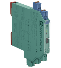
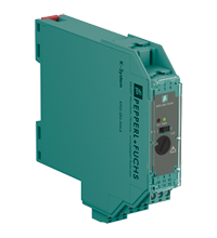
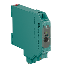
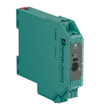
SMART Transmitter Power Supply KCD2-STC-Ex1.ES.SP
- 1-channel isolated barrier
- 24 V DC supply (Power Rail)
- Input for 2-wire SMART transmitters and current sources
- Output for 4 mA ... 20 mA or 1 V ... 5 V
- Sink or source mode
- Line fault detection (LFD)
- Housing width 12.5 mm
- Connection via spring terminals with push-in connection technology
- Up to SIL 3 acc. to IEC 61508


 Contact Us
Please note: All product-related documents, such as certificates, declarations of conformity, etc., which were issued prior to the conversion under the name Pepperl+Fuchs GmbH or Pepperl+Fuchs AG, also apply to Pepperl+Fuchs SE.
Datasheet excerpt: Technical data of KCD2-STC-Ex1.ES.SP
| General specifications | ||
|---|---|---|
| Signal type | Analog input | |
| Functional safety related parameters | ||
| Safety Integrity Level (SIL) | SIL 3 | |
| Supply | ||
| Connection | Power Rail or terminals 9+, 10- | |
| Rated voltage | 19 ... 30 V DC | |
| Ripple | ≤ 10 % | |
| Rated current | ≤ 50 mA | |
| Power dissipation | ≤ 800 mW | |
| Power consumption | ≤ 1.2 W | |
| Input | ||
| Connection side | field side | |
| Connection | terminals 1+, 2-; 3+, 4- | |
| Input signal | 4 ... 20 mA , limited to approx. 27 mA reverse polarity protected | |
| Line fault detection | downscaling ≤ 3 mA ; upscaling ≥ 22 mA | |
| Voltage drop | approx. 5 V on terminals 3+, 4- | |
| Available voltage | ≥ 15 V at 20 mA terminals 1+, 2- | |
| Output | ||
| Connection side | control side | |
| Connection | terminals 5-, 6+ | |
| Load | 0 ... 300 Ω (source mode) | |
| Output signal | 4 ... 20 mA or 1 ... 5 V (on 250 Ω, 0.1 % internal shunt) 4 ... 20 mA (sink mode), operating voltage 16 ... 28 V |
|
| Ripple | 20 mV rms | |
| Fault indication output | ||
| Output type | fault bus signal , open collector transistor | |
| Transfer characteristics | ||
| Deviation | at 20 °C (68 °F) ≤ ± 20 µA incl. calibration, linearity, hysteresis, loads and supply voltage fluctuations (source mode and sink mode 4 ... 20 mA) ≤ 10 mV incl. calibration, linearity, hysteresis and fluctuations of supply voltage (source mode 1 ... 5 V) |
|
| Influence of ambient temperature | < 2 µA/K (0 ... 70 °C (32 ... 158 °F)); < 4 µA/K (-20 ... 0 °C (-4 ... 32 °F)) (source mode and sink mode 4 ... 20 mA) < 0.5 mV/K (0 ... 70 °C (32 ... 158 °F)); < 1 mV/K (-20 ... 0 °C (-4 ... 32 °F)) (source mode 1 ... 5 V) |
|
| Frequency range | field side into the control side: bandwidth with 1 mApp signal 0 ... 3 kHz (-3 dB) control side into the field side: bandwidth with 0.5 Vpp signal 0 ... 3 kHz (-3 dB) |
|
| Settling time | ≤ 200 ms | |
| Rise time/fall time | ≤ 20 ms | |
| Galvanic isolation | ||
| Input/Output | safe electrical isolation acc. to IEC/EN 60079-11, voltage peak value 375 V | |
| Input/power supply | safe electrical isolation acc. to IEC/EN 60079-11, voltage peak value 375 V | |
| Output/power supply | Basic isolation acc. to EN 61010-1 rated insulation voltage ≤ 50 V | |
| Indicators/settings | ||
| Display elements | LEDs | |
| Control elements | DIP switch | |
| Factory setting | output: current source | |
| Configuration | via DIP switches | |
| Labeling | space for labeling at the front | |
| Directive conformity | ||
| Electromagnetic compatibility | ||
| Directive 2014/30/EU | EN 61326-1:2013 (industrial locations) | |
| Conformity | ||
| Electromagnetic compatibility | NE 21:2006 | |
| Degree of protection | IEC 60529:2001 | |
| Ambient conditions | ||
| Ambient temperature | -20 ... 70 °C (-4 ... 158 °F) | |
| Mechanical specifications | ||
| Degree of protection | IP20 | |
| Connection | spring terminals | |
| Mass | approx. 100 g | |
| Dimensions | 12.5 x 114 x 124 mm (0.5 x 4.5 x 4.9 inch) , housing type A2 | |
| Height | 124 mm | |
| Width | 12.5 mm | |
| Length | 114 mm | |
| Mounting | on 35 mm DIN mounting rail acc. to EN 60715:2001 | |
| Data for application in connection with hazardous areas | ||
| EU-type examination certificate | CESI 10 ATEX 071 | |
| Marking |  II (1)G [Ex ia Ga] IIC II (1)D [Ex ia Da] IIIC I (M1) [Ex ia Ma] I II (1)G [Ex ia Ga] IIC II (1)D [Ex ia Da] IIIC I (M1) [Ex ia Ma] I |
|
| Input | Ex ia, Ex iaD | |
| Supply | ||
| Maximum safe voltage | 253 V AC (Attention! Um is no rated voltage.) | |
| Equipment | terminals 1+, 2- | |
| Voltage | 25.2 V | |
| Current | 100 mA | |
| Power | 630 mW | |
| Internal capacitance | 5.7 nF | |
| Internal inductance | negligible | |
| Equipment | terminals 3+, 4- | |
| Voltage | < 30 V | |
| Current | < 128 mA | |
| Voltage | 7.2 V | |
| Current | 100 mA | |
| Power | 25 mW | |
| Internal capacitance | 5.7 nF | |
| Internal inductance | negligible | |
| Certificate | PF 10 CERT 1749 X | |
| Marking | II 3G Ex nA IIC T4 Gc |
|
| Directive conformity | ||
| Directive 2014/34/EU | EN 60079-0:2012+A11:2013 , EN 60079-11:2012 , EN 60079-15:2010 | |
| International approvals | ||
| UL approval | ||
| Control drawing | 116-0378 (cULus) | |
| IECEx approval | ||
| IECEx certificate | IECEx CES 11.0001 | |
| General information | ||
| Supplementary information | Observe the certificates, declarations of conformity, instruction manuals, and manuals where applicable. For information see www.pepperl-fuchs.com. | |
| Accessories | ||
| Optional accessories | - power feed module KFD2-EB2(.R4A.B)(.SP) - universal power rail UPR-03(-M)(-S) - profile rail K-DUCT-BU(-UPR-03) |
|
Classifications
| System | Classcode |
|---|---|
| ECLASS 13.0 | 27210119 |
| ECLASS 12.0 | 27210119 |
| ECLASS 11.0 | 27210119 |
| ECLASS 10.0.1 | 27210119 |
| ECLASS 9.0 | 27210119 |
| ECLASS 8.0 | 27210119 |
| ECLASS 5.1 | 27210119 |
| ETIM 9.0 | EC001485 |
| ETIM 8.0 | EC001485 |
| ETIM 7.0 | EC001485 |
| ETIM 6.0 | EC001485 |
| ETIM 5.0 | EC001485 |
| UNSPSC 12.1 | 32101514 |
Details: KCD2-STC-Ex1.ES.SP
This isolated barrier is used for intrinsic safety applications.
The device supplies 2-wire transmitters in the hazardous area, and can also be used with current sources.
The device transfers the analog input signal to the non-hazardous area as an isolated current value.
Bi-directional communication is supported for SMART transmitters that use current modulation to transmit data and voltage modulation to receive data.
The output is selected as a current source, current sink, or voltage source via DIP switches.
A fault is signalized by LEDs and a separate collective error message output.
Test sockets for the connection of HART communicators are integrated into the terminals of the device.
Datasheet: KCD2-STC-Ex1.ES.SP
| Datasheet | File Type | File Size |
|---|---|---|
| Datasheet KCD2-STC-Ex1.ES.SP | 361 KB | |
| Fiche de données KCD2-STC-Ex1.ES.SP | 426 KB | |
| Datenblatt KCD2-STC-Ex1.ES.SP | 358 KB | |
| Datasheet KCD2-STC-Ex1.ES.SP | 494 KB | |
| Hoja de datos KCD2-STC-Ex1.ES.SP | 451 KB |
Documents: KCD2-STC-Ex1.ES.SP
| Manuals | File Type | File Size |
|---|---|---|
| Manual | 3685 KB | |
| Safety Manual | 427 KB | |
| Handbuch | 3693 KB | |
| Safety Manual | 2430 KB | |
| Instruction manuals | ||
| Инструкции | 69 KB | |
| Návod k poużití | 61 KB | |
| Instruktions manual | 58 KB | |
| Instruction manual | 50 KB | |
| Kasutusjuhend | 56 KB | |
| Käyttöohje | 56 KB | |
| Manuel d'instructions | 97 KB | |
| Betriebsanleitung | 62 KB | |
| Οδηγίες χρήσης | 73 KB | |
| Handleiding | 72 KB | |
| Instruction manual / Betriebsanleitung | 70 KB | |
| Használati útmutató | 71 KB | |
| Manuale di istruzioni | 93 KB | |
| Lietošanas pamācība | 68 KB | |
| Instrukciju vadovas | 68 KB | |
| Instrukcja obsługi | 72 KB | |
| Manual de instruções | 72 KB | |
| Manual de utilizare | 71 KB | |
| Návod na poużitie | 130 KB | |
| Manual de instrucciones | 95 KB | |
| Manual | 66 KB |
CAD+CAE: KCD2-STC-Ex1.ES.SP
| CAD | File Type | File Size |
|---|---|---|
| CAD 2-D / CAD 2-D | ZIP | 458 KB |
| CAD 3-D / CAD 3-D | STP | 179 KB |
| CAD Portal / CAD Portal | LINK | --- |
Approvals+Certificates: KCD2-STC-Ex1.ES.SP
| Certificates | File Type | File Size |
|---|---|---|
| Europe CESI I (M1) II (1) G II (1) D ATEX Category | 629 KB | |
| Europe Pepperl+Fuchs ATEX Category 3 G Certificate | 194 KB | |
| TÜV SÜD Functional Safety Certificate | 188 KB | |
| USA Canada UL Hazardous Location Certificate of Compliance cULus UL E106378 | 413 KB | |
| Worldwide CESI IECEx Certificate of Conformity | LINK | --- |
| Control Drawings | ||
| Control drawing UL / Control drawing UL | 128 KB |
Associated Products: KCD2-STC-Ex1.ES.SP
| Accessories | ||||||
|---|---|---|---|---|---|---|
|
||||||
|
||||||
|
||||||
|
||||||
|
||||||
|
||||||
|
||||||
|
||||||
|
||||||


Pepperl+Fuchs Inc.
1600 Enterprise Parkway
Twinsburg, OH 44087
United States of America
sales@us.pepperl-fuchs.com
 +1 330 425-3555
Pepperl+Fuchs is a leading developer and manufacturer of electronic sensors and components for the global automation market. Continuous innovation, enduring quality, and steady growth have been the foundation of our success for more than 70 years. Pepperl+Fuchs employs 6,300 people worldwide and has manufacturing facilities in Germany, USA, Singapore, Hungary, Indonesia and Vietnam, most of them ISO 9001 certified. Pepperl+Fuchs does not sell personal data.